There are very few bikes that get used on dirt that don’t require a bent seat tube to work properly. Tires have grown, chainstays are short, and pretty much everything uses a dropper post. Today’s dropper posts stroke around 150 mm to 200 mm, 170-185 mm is preferred. These factors combined with the need to get the saddle in the correct position for the rider and use of the bike make for a challenge that only a bent seat tube will solve.
A while back I did some work to define how a bent seat tube is set in a fixture and how the tube would be described in BikeCAD. Don at Anvil produced an addition to his fixtures based on my modifications and Brent added features to BikeCAD that would produce the needed dimensions. I believe that that helped many of the people confused about working with bent seat tubes. That got the tube described and placed for construction but it did nothing about placing it within the design.
As I’ve just shipped a production run of my cutting edge bent seat tubes to a few builders, I figured that it was a good time to talk about the really fine points of building with these tubes. Bent seat tubes aren’t for the faint of heart or those without good CAD skills.
My bent seat tubes were designed to work as well as possible in the modern ecosystem. The super tight 3.0″ center line radius is an engineering choice that was dictated by the parameters needed in a frame design. I paid a premium to get this bend done so you can believe that it was for very good reason. I’ve been producing my own bent seat tubes since 2013 and this has informed my learning. Some other folks who have just begun producing bent tubes with 17.0″ CLR or even 8.0″ CLR really don’t come close to accomplishing what the tight bend does.

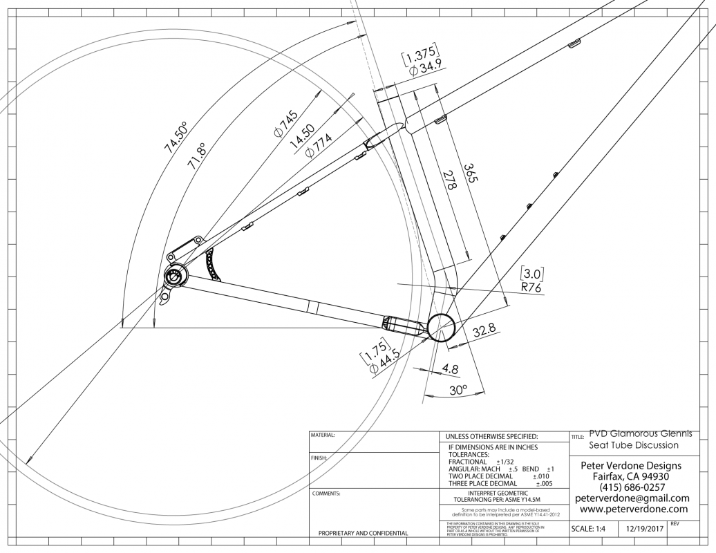
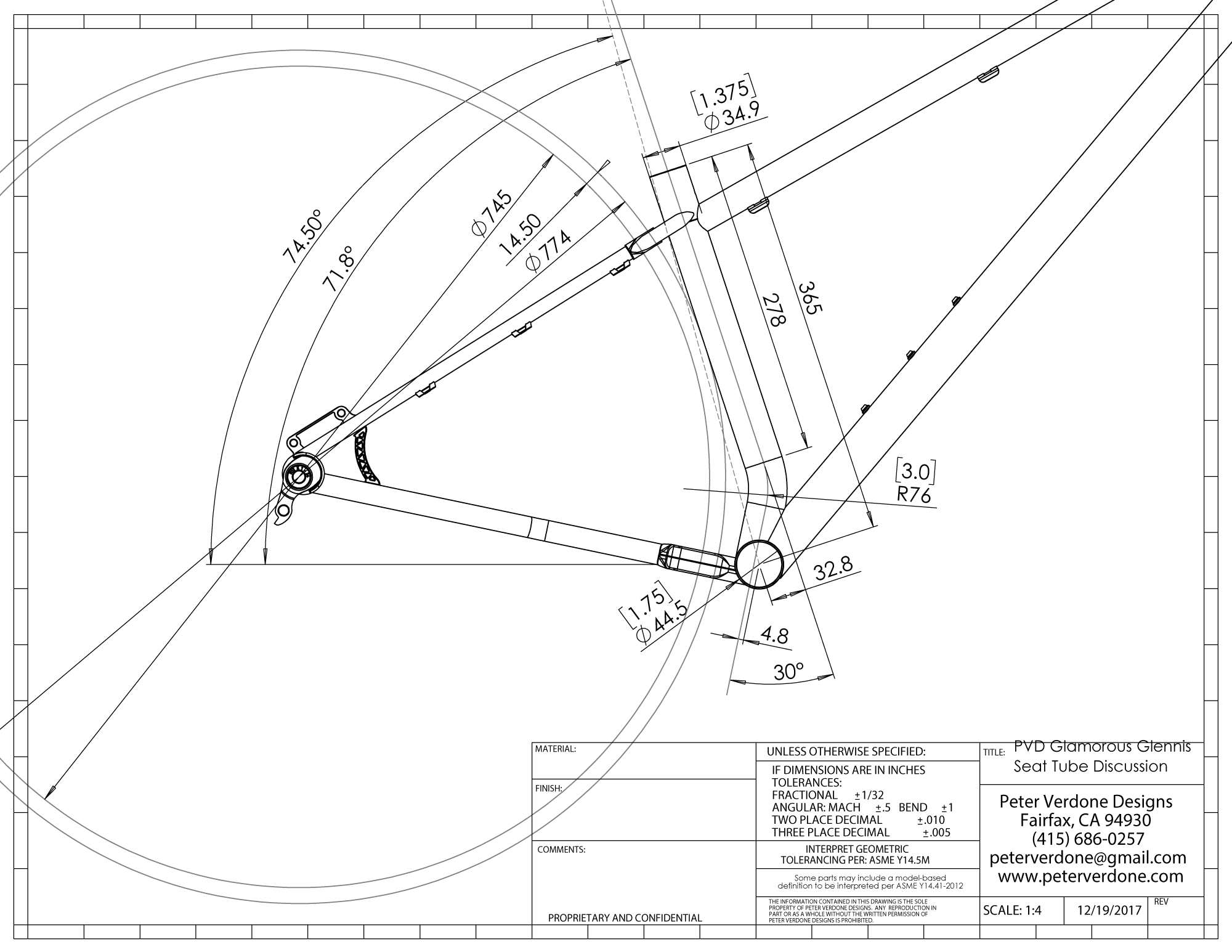
The image below includes some of the pertinent details for properly placing a tube in a frame.
The goal when placing the tube in a design is to have the steepest actual seat tube angle given a desired effective seat tube angle (here shown @ 74.5°). We also look to ensure that the greatest straight line segment is produced for the seat post and plumbing to use. To accomplish this, we place the seat tube tangent to the arc defining the maximum clearance diameter the stays or yokes allow, here 774 mm diameter. If the seat tube is any farther from the tire than this clearance arc tangent, the design is compromised.
By placing the tube this way:
- The available dropper post, hose, and seat drop space is maximized
- The bending load on the dropper post is minimized
- The friction and drive angle to actuate the post is kept low (a legitimate concern)
- The variances in longitudinal saddle position with changes in height are minimized
I like to have my seat tube connect tangent and to the rear with the bottom bracket although this is a detail that can be left to the frame builder. It costs me a few millimeters of post clearance but it helps the structure of the bike considerably.
It is important that the desire to place the bend in reference to the tire for cosmetic reasons not be done. This is a failure of reason, placing fashion in front of function, and will result in a poor-riding bike and fewer part options for the user. This choice will highly restrict the post options. It will also make such a slack angle that actuating the dropper will be difficult and the longitudinal change in saddle position with height be great.
It is also important to design a seat tube that uses a 31.6 mm ream and a long interface area in the frame. I use 4″ inserts that I make for the tube although Paragon makes perfectly fine 3.5″ versions. This is the correct diameter for dropper posts in a modern bike. The reason is that it gives the post itself a thicker wall and support in the slide region of its structure to remain dimensionally stable while being subjected to bending loads. Dropper posts are all of a tenuous design and need to be given every advantage they can get to work as best they can. Additionally, for steel and titanium builders it’s lighter, replacing heavy material for light aluminum. Long stroke posts are also extended very far from the frame and the leverage they have going into the frame is very high. This is a real consideration. Additionally, a 31.6 mm frame ream will fit a 31.6 mm diameter seatpost as well as a 30.9 mm diameter seatpost, so the customer is served by this choice.

Note that the sketched clearance diameter is tangent to the chainstay yoke, seatstay yoke, and the seat tube. It is hard to show that here without overly confusing drawings.

