Toolmaking has been a theme lately. After putting time into my frame fixture tooling and my press tooling and a lingering mandrel bending project. I’m hoping to get back to some go fast shit soon.
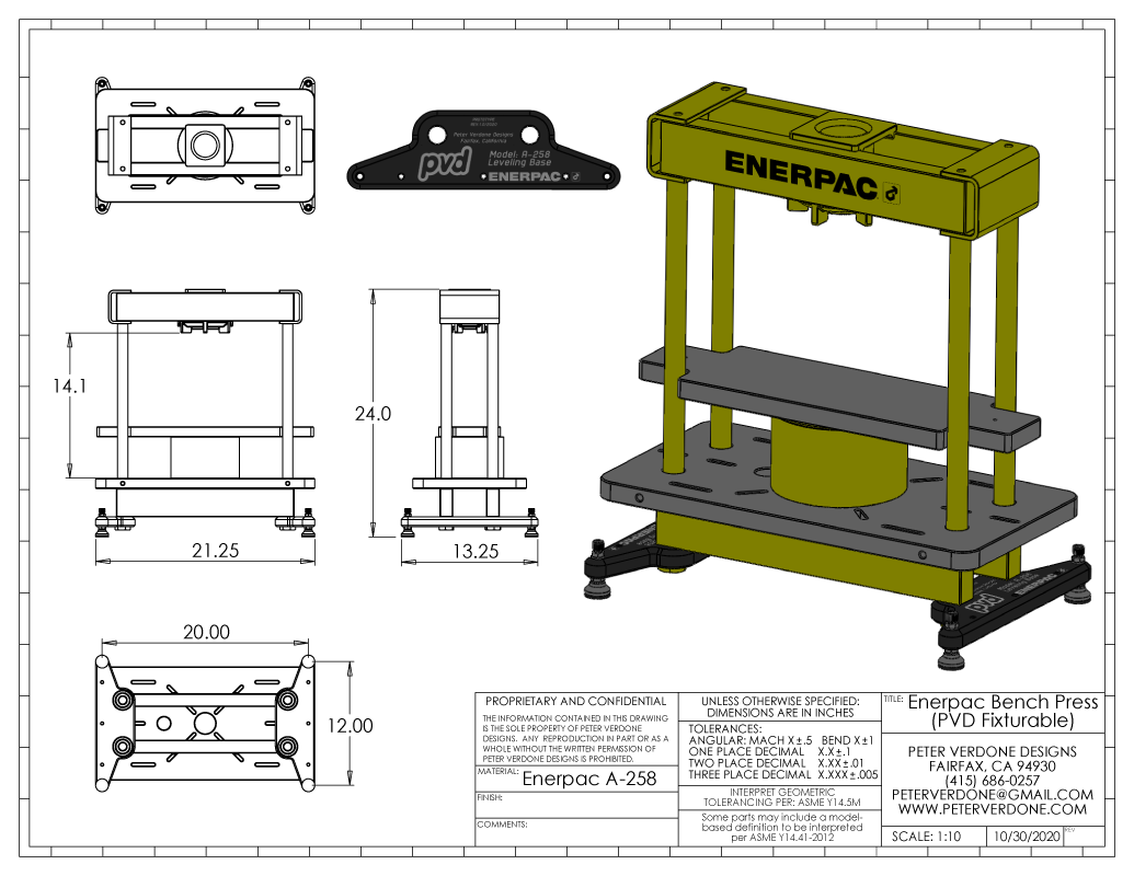
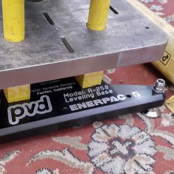
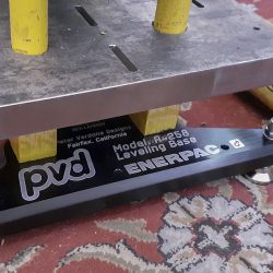
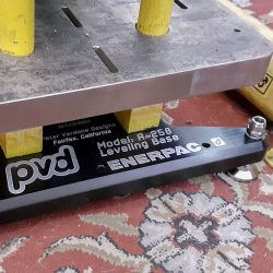
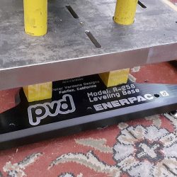
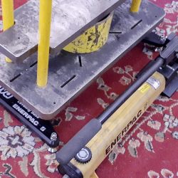
I finished the leveling base plates for my Enerpac press a while ago. They have been an awesome improvement to the tool and something missing in the original design but they really weren’t done. Bare aluminum parts have become my enemy. The plates needed to be anodized and marked. Just like a bicycle, a machined part isn’t done until it has a color job and rust proofing. I didn’t have enough parts going to anodize to justify a special run so they sat for a while and waited. Luckily, Ronen was sending some parts in and I was able to glom onto his load and get my plates done.
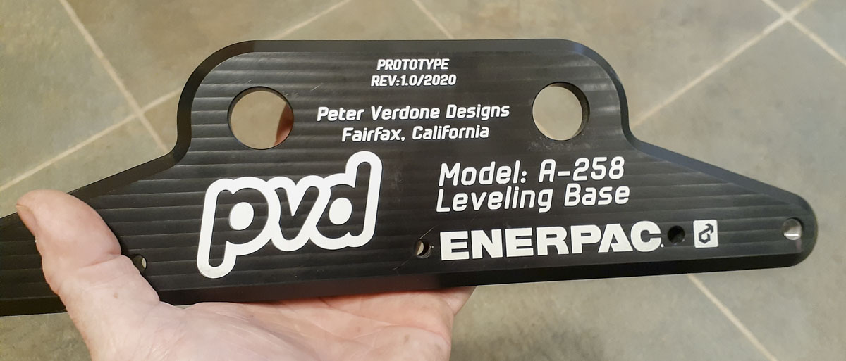
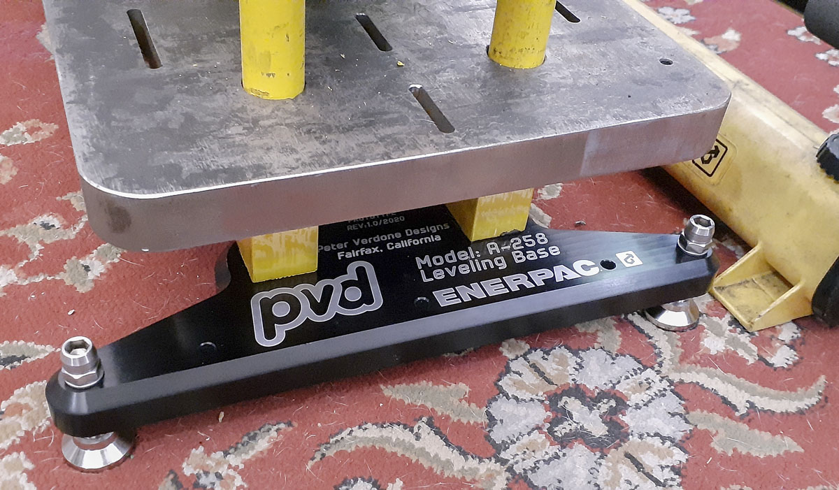
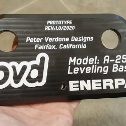
After getting the blackened parts back, I marked them with the fiber laser and it came out nice. I’ve gotten the marking system down well. It takes a bit of time to ensure but that’s for exceptional results.
I used my longest lens, the f420 with a 300mm x 300mm scan area to do this. The entire graphic was just a bit over the range of the f290 (200mm x 200mm). On other large parts (like those on the frame fixture) I have broken up areas to be marked so that I could use shorter lenses. This made the precision easier to hold and minimized power loss. Since this was just cosmetic graphic, I could play with the long lens. I had to do a full calibration and I did some housekeeping with my EasyCad2 file structure (branding and lens specified). The calibration is a bit of an issue with such a long lens. I got it close enough for this use but I will have to do more work for next time I use it.
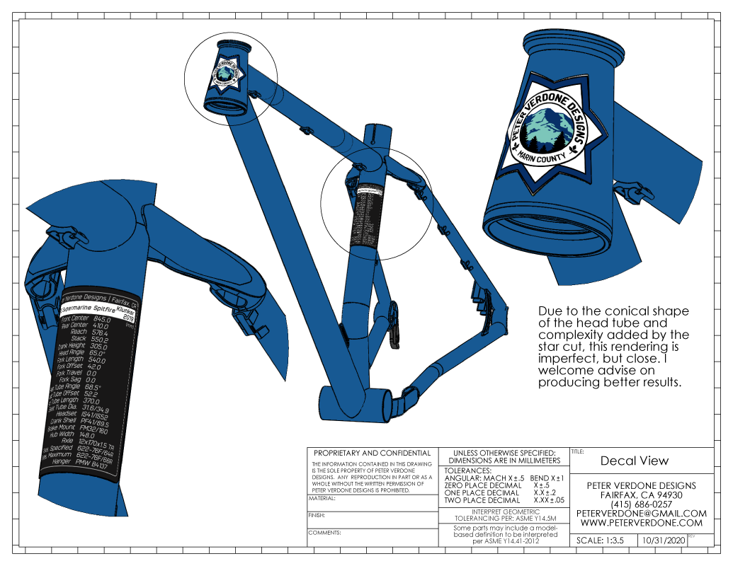
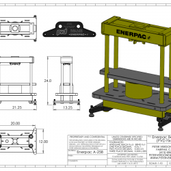
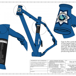
Something that I’ve been doing with modeling and since I started using lasers to mark on my data plates and after, has been to ensure that I’m modeling all the “2D” markings in the solid models. This gives me a really good idea of how the graphics will look on the actual finished product. I’ve used it while designing my decals, the markings for my frame fixture, and a host of other designs in the works.
This makes a real difference. In the example today, you can see that the plate beams extend over the leveling base. I needed to ensure that the graphic would look good from all angles with this. I decided to tuck the smaller descriptive text in between the beams as they would have just been clutter otherwise.
What I’m showing here is a very simple graphic. Don’t let that fool you. Several hours were consumed with laying it out and making the choices in it’s design. Four real iterations were tried and a bunch of fine adjustment before it came together. Is it production perfect? Hell no. I’m a terrible graphic designer. Still, by using the method that I’m describing, I was able to sort the terrible ideas from the part before it was rendered garbage. This is an important tool and would be even more powerful if I had any real skill to use it.
I highly recommend folks not skip this step when producing finished good. A 3D model is priceless and can have value extracted in lots of ways. Do the detail work, it pays back.
