Difference between revisions of "Speedometer Calibration"
| Line 13: | Line 13: | ||
| − | + | [[Image:Speedochart.gif]] | |
Revision as of 15:44, 19 October 2006
After re-gearing my bike (F4i) from 16/46 to 15/50 and changing tires, I figured that my speedo would be off by at least a factor of 1.135 (math).
Modern sport bikes use a pulse generator on the countershaft in the gearbox to gauge bike speed rather than the older system of gearing a spinning shaft off of the rotation of the front wheel. The older system would add error to the speedo anytime the front wheel or tire changed diameters. The current system will add error anytime the rear wheel or tire changes diameter AND/OR when the final drive gear ratio is changed. The diameter also changes at speed, so any speedo can only be "correct" at one speed.
I ordered a Yellow Box Speedometer Re-calibrator (www.blackrobotics.com) to correct this. The Yellow Box takes the signal from the pulse generator and modifies it by a determined factor (adjustable) to produce a corrected pulse signal that the speedometer and ECM will use to gauge speed. The pulse can be corrected to the nearest 0.25%. Also see: J. Ahlman Designs Recalibrator or Speedohealer for other plug-n-play alternatives.
After studying my bikes wiring diagram, I made a custom jumper using some junk old harness parts (Honda 3-pin disconnects) so that I would not have to cut my stock parts or wiring harness. While researching the install of this part, I had read online that someone jumped into the harness near the speedometer. The wiring diagram shows that the pink (pulse) line splits just after the pulse sender with one end going to the ECM and the other going to the speedometer. If the pulse is not corrected JUST after the pulse sender, the computer gets one speed pulse while the speedo will get another. This could have poor affects on the speed based fuel compensation for the ram air and gear based mapping features on most current bikes. The Yellow Box MUST jump the line AT the pulse sender.
The length of the wires that come on the Yellow Box are just long enough to be routed to the rear of the bike's glove box. I velcroed my Yellow Box right next to my Power Commander. When installing the Yellow Box the way that I have noted, make sure to cut as little of the Yellow Box's wires as you have to or it will not reach the best mounting position.
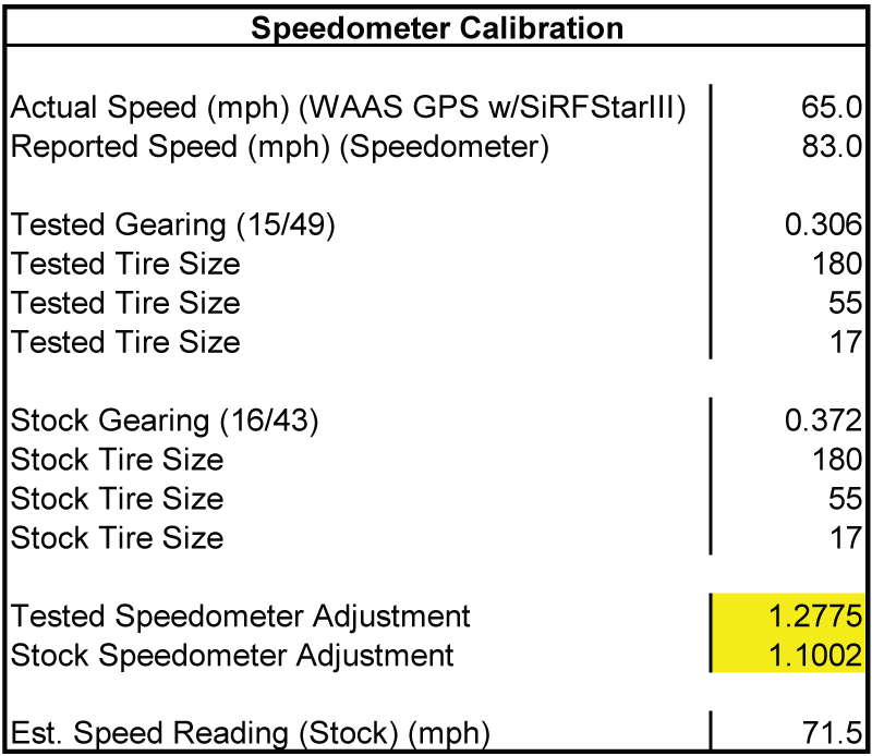
When dialing the speedo in at a local police speed billboard, it was out by a factor of 1.135 with non stock 15/47 gears. This is yet another example that the real world vs. calculations can be off by considerable margins. This gives me a built in speedo error factor of 1.045. Once you have a tested and proven correction factor given any gearing, you can correct for gear changes without testing the vehicle again. Now that I have re-geared to 15/50 (dropped back to 15/49 just after this) I know that my correction factor will be 1.205. It works like this:
One additional part of this job that you may consider is jumping an auxiluary power line off of the pulse sender line. Since I had to bring the Yellowbox back to the glovebox anyway, I placed a two pin connector on the same line. My laptimer requires a 12 volt power supply, so this will be perfect. This is better than jumping off the battery since the line goes dead when power is off on the bike. Jumping off the battery requires an additional switch.
