This is a bit of a continuation of a past post about the new mathematical considerations that the newer all-road/gravel suspension forks have in calculating bike geometry.
Because the sliders are set at an angle to the steerer (and thus, the head tube), calculating the bike geometry at a given location in the fork travel has become quite complex.
I had this information available to me in the past but it’s taken a while to update for the new forks.. This week I found the time.
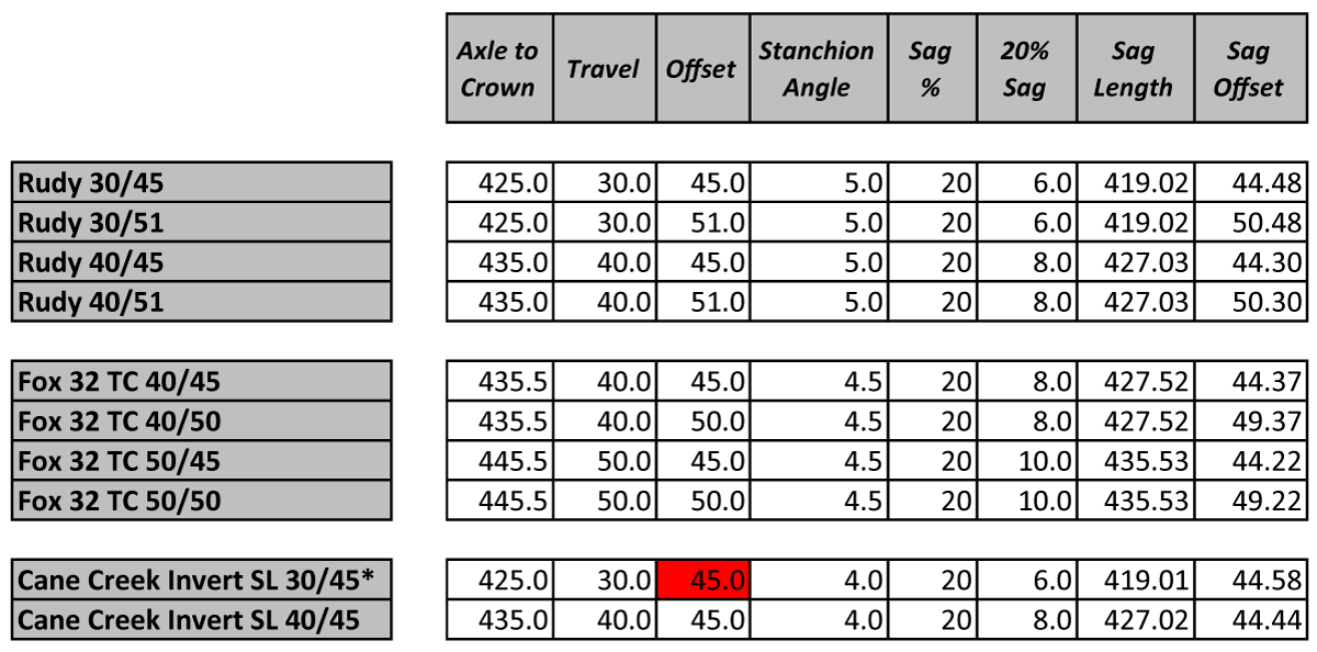
Here’s a selection of forks that some might choose. I’m really feeling that the data is being reported in a suspect way. Knowing that a short version of one fork will be a change in travel, the axle to crown and the offset for that fork should be trigonometrically factor of the stanchion angle. I don’t see that, so I would confirm values.
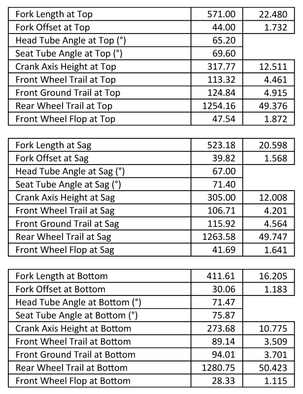
Here’s a way of seeing what happens in the design. To make the numbers more dramatic, I copied the data from my 2023 Millenium Falcon MTB and changed the fork data to have a 5 degree stanchion angle from the steerer.
The math to get these values was pretty complex but not advanced. It’s just high school trigonometry applied to a real world situation. Give it a shot.
Within all the data, the crank axis height at the bottom of the fork travel is the most valuable. 273.7mm is low but not crazy. If this is the limit, I can target other bikes to have a similar value at the bottom of the stroke regardless of other geometries.
I can also use the topped out information to compare to other builders bikes that aren’t reporting their geometry in a sensible way.
This is just useful information that we should have available when making decisions about a bike design. It’s not a rule but informs the picture of what is happening.


