The other day, I was in a discussion with a student that was running some queries on my site. He told me that since starting my blog in 2010, I’ve posted, on average, once a week, every week. In blog land, that ultra marathon world cup performance. It’s been a while since my last post. I’ve just brought that average down. That was August 27, over seven weeks ago. That’s how rare this gap is. There are several reasons for this; work, a new class, malaise, a deep project, feeling useless, and more.
The Samantha frame fixture is getting refit. A few upgrades and fixes. Great is getting better. Part of this is improving the method for calibrating the crank shell and axle towers for perpendicularity to the working surface, and thus, the center-plane of the frame. This is very serious for getting right. Small errors here result in large problems elsewhere.
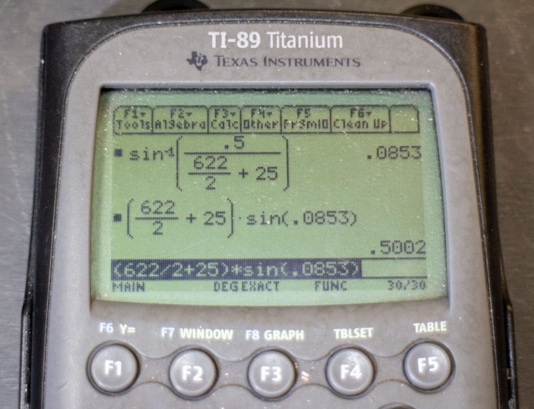
For example, if the rear axle is centered on the frame center plane but is not precisely perpendicular to it, the edge of the tire will shift to one side, out from the rear axle location. For a 622mm BSD wheel and with the tire’s widest point 25mm from the bead seat, we are looking at the area 336mm from the axle. A deviation of just 0.0853 degrees (0°5’6.94”) from perpendicular to the frame center-plane will see the tire move to one side 0.50mm. This will look worse than that as actually is as it’s also moving away from the other side by the same amount. So a perceived 1.00mm ‘error’ of the tire between the stays.
That amount of error is pretty bad in bike building. I would want to keep any deviation under 0.25mm from center at the tire edge. This means that for the rear axle, the fixture and resulting frame interface need to be less than 0.043° or 2’33.5” from perpendicular to the center-plane. This, again, is crucial.
How to measure this and calibrate the fixture is the issue. There are several strategies. In an earlier post, I put some work into a laser system to be able to measure a virtual plane over the table. This was a handy setup but proved to have issues for high levels of precision as the laser dot size impeded fine registration.
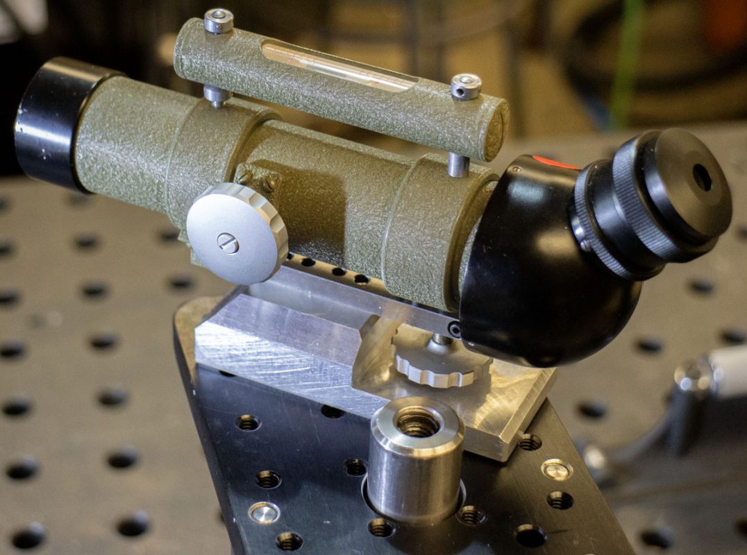
The lesson in that development was that optics would be needed to measure with real precision. That meant I’d need a cathetometer mounted to the shell and axle pillars. Cathetometers are expensive. It took a few months but I was able to get one on Ebay for just less than $200. The optics of the cathetometer I received has a 10x magnification. It would be better to have a 20x similar to the cheap auto-level referenced in the previous post. That’s something to deal with another day.
A base had to be made so that the scope could be floated on a surface. I designed one so that it centered the mass over the center of the base so that it wouldn’t be to pesky to play with.
A strange story but while making the surface mount for the cathetometer, I found that the threading on the base was M5x0.9. Very strange. M5x0.8 is almost universal these days. My speculation is that this was made in some Eastern Block nation 70 or 80 years ago. I’d love it if someone knows more about this would contact me. The tool is not labeled.
While setting up the cathetometer, I found that it’s level was pulling me away from this method. It was looking useful. This caused me to get distracted again by methods for referencing level.
Level is a tricky issue on this table. Not exactly level but the flatness problem that comes up from the construction of the table. I discuss calibrating the flatness and leveling my shop’s Rhino Cart in a previous post. Despite that, the remaining waviness and slight deviation means that local level on the table remains a challenge when looked at with a fine scale.
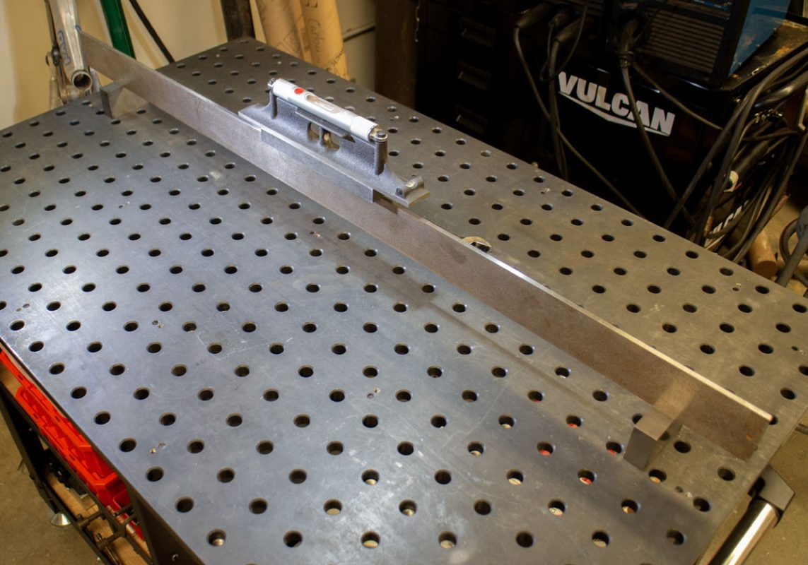
I went into this again and developed a new method for tuning the flatness of the the table that should help the reference going forward. This turned out to be a much nicer solution than my previous methods. This involved using a level rather than feeler gauge.
- Loosen the top plate attachment screws slightly to free it to rise from the frame.
- From just touched off on the frame, screw the calibration screws in about 1 turn to raise the top plate away from the frame. This gives some adjustment room in a second direction.
- Lightly tighten the top plate attachment screws.
- At one corner (the base corner), above the leveling foot, place the end of a straight edge. The second end of the straight edge should be placed over the far diagonal corner. The straight edge should be resting on a 123 or suitable parallel block.
- Adjust the leveling feet to bring these two corners to level.
- Continuing leveling the other two corners.
- Repeat the corner leveling from the base corner until you are confident that no adjustment is needed.
- Using the level between adjustment screws, fanning radially from the base corner, set local level. It may help to adjust the most egregious local level issue first.
- Fully tighten the top plate attachment screws.
- Repeat and address any local level issues
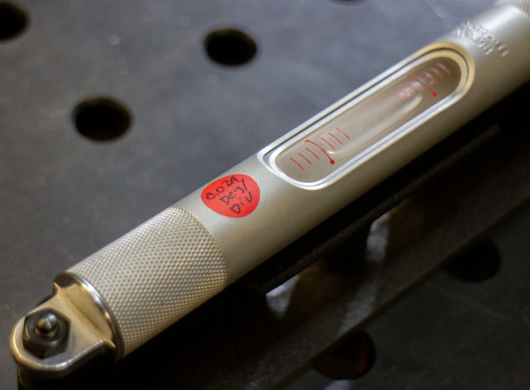
How well level can be achieved depends on the construction and adjustments available in the table but also the SENSITIVITY of the level used. Sensitivity refers to the registration to displacement that a spirit level vial will show. Using a vial that isn’t sensitive enough will result in a table that is not level enough to produce acceptable results. A vial that is overly sensitive will result in much wasted time chasing level that isn’t significant and is beyond the requirements at hand.
Shopping for a level is not easy. Many levels have marketing that pages fail to mention the sensitivity of the tool. Others use a metric that varies or is vague. DMS and decimal degrees are swapped at random. Most are metric but pretend to be imperial. It’s very frustrating. For reference, here’s some common level vial sensitivity (DIN2276/877).
0.050″/foot = 0.239°/div (0.10″) or 14’19.4”/div (0.10″) – Carpentry
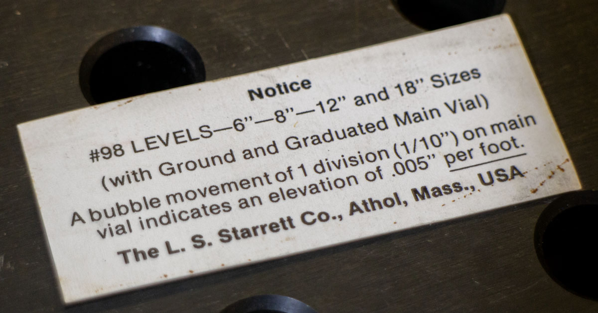
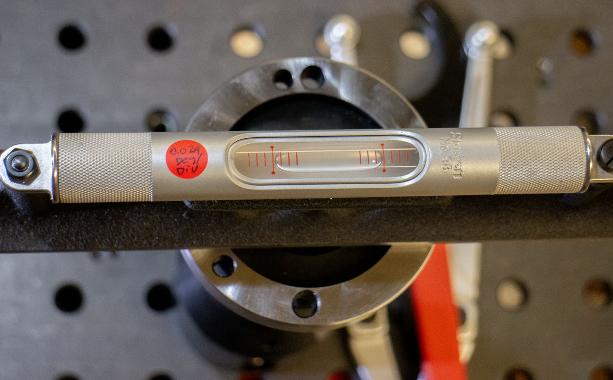
0.005″/foot = 0.024°/div (0.10″) or 1’25.9”/div (0.10″) – Machinist
0.0005″/foot = 0.002°/div (0.10″) or 8.6”/div (0.10″) – Machine Leveling
1.0mm/m = 0.057°/div (2mm) or 3’26.3”/div (2mm)
0.1mm/m = 0.006°/div (2mm) or 20.6”/div (2mm)
0.02mm/m = 0.001°/div (2mm) or 4.1”/div (2mm)
It may be that I should be using a tool that is a little less sensitive than a machinist level but not as rough as a carpentry level. At this point, I’m using my 0.005″/foot Starrett 98-12 machinist level. This is where I’ve gotten to. Later I hope to have a Starrett 98-4 or something similar. Maybe a 100mm digital level that reads to 0.01° would be nicer.
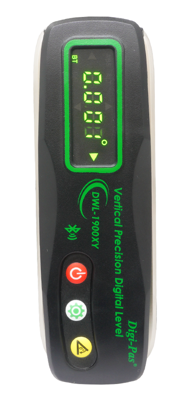
Digi-Pas makes a very nice 2-Axis Vertical Precision Digital Level (DWL-1900XY) with sensitivity to 0.001°. While that is too sensitive for this work, it’s nothing that a little PVC tape can’t solve. The tool costs $475 but that may make for a nice gift next year. A Digi-Pas DWL-1500XY 2-Axis Horizontal Precision Digital Level brings the price down to $375. The big problem with either of these digital level options is that the range of use is ± 5.000° or 2.000° respectfully. Therefor it has little use for measuring odd angles that would be handy in other projects. It’s insane that through their app, you can use two of these to measure perpendicularity in real time. Money really does buy happiness.
While researching spirit levels, I found a 160mm frame level from Amazon for $50 and had to grab it. This tool can measure the perpendicularity of the pillars directly. While this would be perfect, it is very awkward given the sensitivity of the vial. 0.02mm/m is far too sensitive for me to use effectively here. It wastes too much time chasing a degree of level that is no longer useful. I believe that a 100mm version but with a less sensitive vial would be a really nice tool at the table. Some plastic printed clips would hold it fast to a shaft for ease of use.
A $15 surveyor’s rod level is a nice little tool, the problem here is that the tiny 15mm vial bullseye level is incapable of the sensitivity needed for this application and is difficult to read. Two types are common, the vee groove style and the binder style. The viewer has to look directly down to see deviation. It is a nice little tool and worth copying later with a better 60mm vial. I’ll keep this on hand for rough fab work.
So, at this point after significant research, I’m trying to figure how can it get easier to calibrate this fixture? Can I produce even more value in that solution for projects going forward?
After going down many dark holes and bad ideas, I did end up with a great solution. An 100mm ER40 collet chuck. I happen to have one of these for use on my laser engraver along with a cheap Chinese 1.000″ collet.
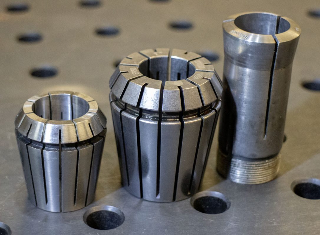
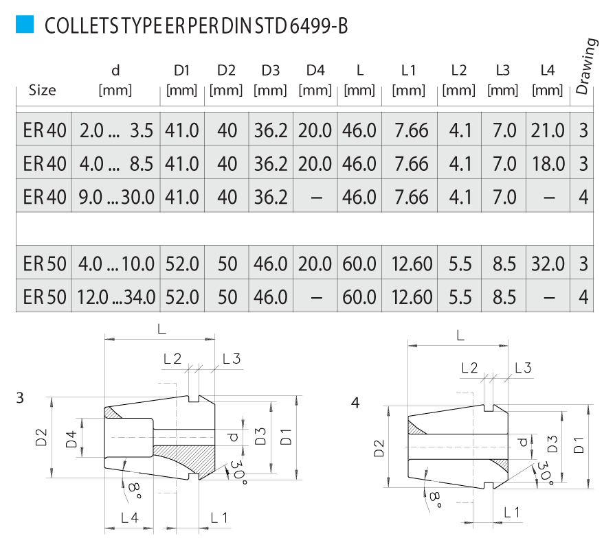
It may be convenient for one to imagine using a 5C collet chuck in this case, but that would be a mistake. A 5C collet has far less engagement of a shaft and taper than even this ER40 collet. The 5C is optimized for holding work shallow toward the mouth while the ER collet is optimized for holding a concentric shaft. There really is a massive difference in this application. Look at how the ER50 collet dwarfs the 5C collet in several ways.
While the ER40 collet setup looked pretty good, I decided to step up to an ER50 collet chuck. The ER50 collet has effectively 30% more conical and shaft engagement. This will help getting as much easy precision from the setup as possible. This may be a bit over the top but that is the game I’m playing now.
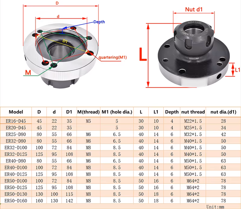
I found a crappy 100mm ER50 collet chuck on Amazon for $35. That seemed like an easy bet to try even if it lacks a high degree of precision due to the low cost. Free Prime delivery in 2 days can’t be argued with. I could have shopped it out and spent more on a 160mm diameter chuck but I figured that $35 was too cheap to ignore in the short run. Over time, I expect to own the 160mm.
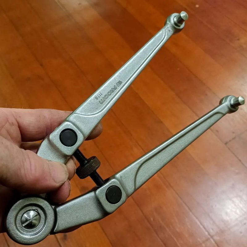
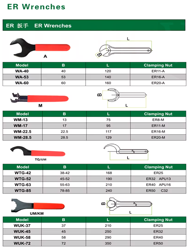
For wrenching the collet chuck, two tools should be used. An ER nut wrench and a nice pin tool. The quartering holes are about 8.9mm around a 84mm bolt circle. The Facom 117.B, 20 – 100 mm Compass Wrench is one of those tools. Using both these tools correctly, very little nudging will be imparted on the system while offering significant torque.
A low cost ER50 collet was harder to find in the imperial 1.000″ size. Low cost metric ER50 collets are widely available online but their imperial counterparts come at a premium. I ended up sourcing a Techniks 04250-1 : ER 50 1″ Collet from Zoro for $50 (20% discount and free shipping applied). This has a marketed T.I.R. of 0.0002″, which will be far better than the ER40 version I already had. Ordering collets may get more comfortable once I have the mating parts all sorted and in the system.
This arrangement allows me to set up a plane platform perpendicular to the shaft axis anywhere along it. It’s made of hard ground steel which reduces wear. It’s also very elegant and extendable to any size shaft that I have a collet for.
I tested the repeatability of the ER chuck on the shaft. It’s well within my needs. A small piece of optical breadboard gives me a working surface for the cathetometer, lasers, levels, or tooling.
I can already hear Ronen screaming at the monitor that using a collet to hold this is not a proper use of kinematic constraints. True! That’s entirely correct. Using tapered cones with changing relationships to connect to the shaft introduces some ambiguity to the system. Granted, there are plenty of machinists using ER collets with cutting tools and lathes for any manner of precision work.
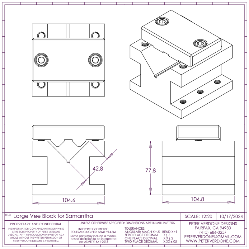
So I checked that. I made a nice clamp for my largest shop vee block. I checked the runout on the lathe for the side face to the vee clamped on a hard 1.000″ shaft. Very nice. Then I clamped the vee-block to the pillars and checked the difference against the calibration with the ER collet chuck. It was imperceptible. I’m not saying the there was no difference, just not one that is meaningful in the context of my system. I’ll take the elegant setup!
I think that I’ve got this pretty much sorted. A nice ER40/50 collet on a halfway usable ER collet chuck works fine for confirming perpendicularity to level in my fixture.
The Wyler A47 Angle level. A very expensive ($1050) tool. I don’t own one.
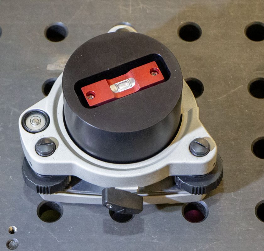
I still haven’t forgotten about the tribrach setups for the table. Shown here with a Seco #2002-00 Adjuster. This will turn into something later.
The calibration elements set up on the fixture in the assembly model.


