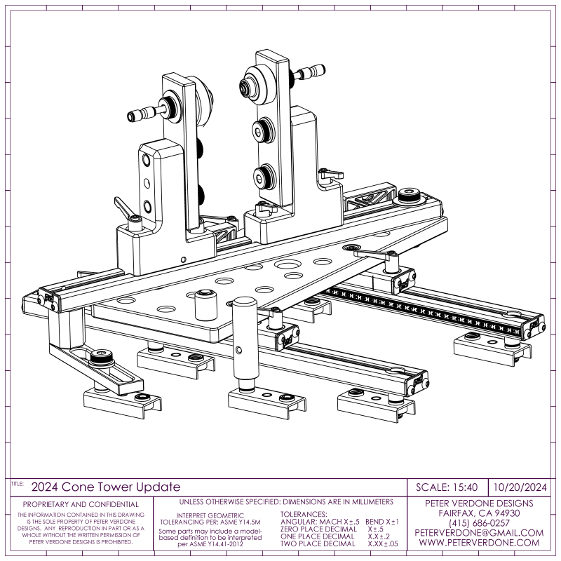
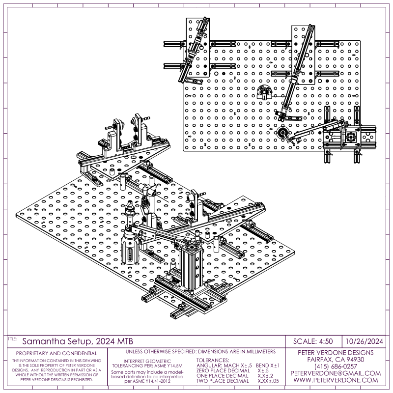
I’ve just completed another round of major upgrades to the Samantha frame fixture. I don’t intend on bringing development to an end as there keep being new territories to explore and old ones to remediate. It just gets better and better.
Firstly, I took some time exploring parts that a re-design that would give me more access when welding in the fixture. A few rounds of ideas were roughed out while considering the new raised center plane height of 240mm. That’s 20mm higher than Samantha had originally been designed for. All for increased welding access. This is up from the 140mm on the Cyberdyne fixture. 100mm higher than Cyberdyne.
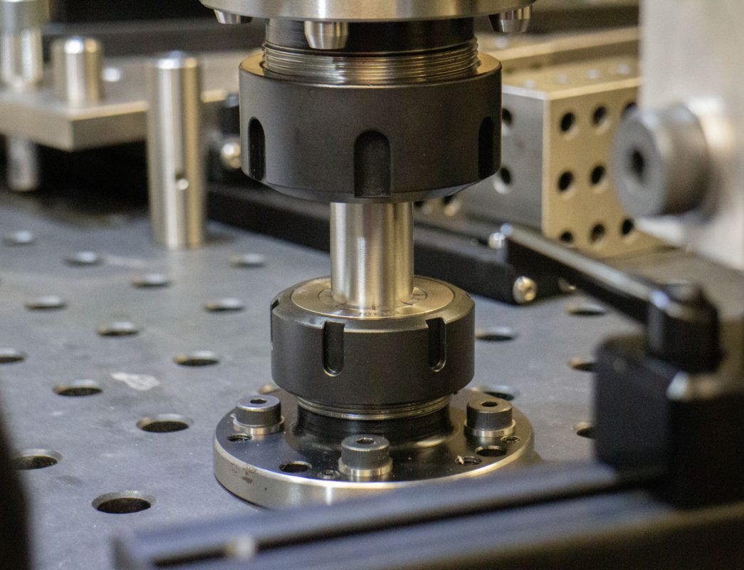
As discussed in an earlier post, improvements were made to the method of flattening of the RhinoCart table top and calibration of the crank shell and rear axle pillars. This turned into a new auxiliary pillar concept that should prove valuable. I love when I start working on one part of the fixture and it turns into entirely new ideas in another part.
This gets us to the real meat of the changes. In the initial design of the Samantha fixture, I was trying to ensure that the various components of the tool were as extendable as possible. Each component should be as re-configurable as prudent so that it could perform unintended and unforeseen roles. This meant that future upgrades and modifications could be made as easy and cheaply. There are many other projects besides bicycle frames that could be made easier with this tooling on hand. Fine details in the Samantha design lends itself to this. But this can go too far.
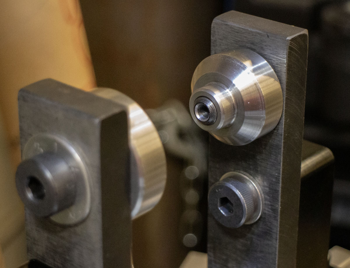
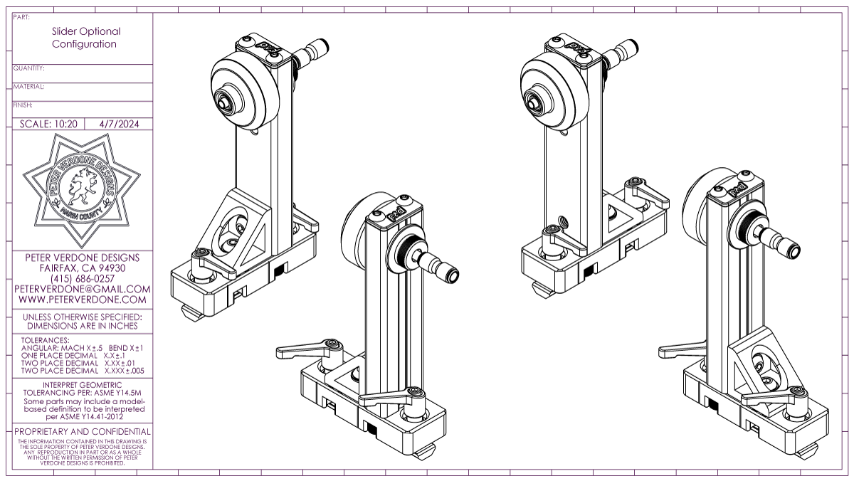
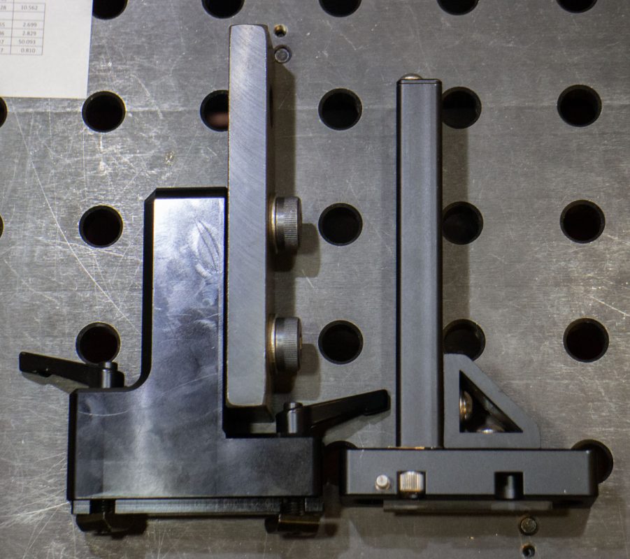
The initial cone towers, as I designed them, were the product of flawed thinking. The 8020 1575-Black-FB profile connected to the rails as they were are problematic. The pins and bolts used to attach the profile to the sliding base along with the 8020 4332-Black corner bracket were not up to the level of precision, rigidity, and holding that I felt necessary. The stackup of geometric relationships produced some yawing of cone from the rail center-plane that I had to work to remove. This was not what I was planning for as minimal calibration should be needed when parts are swapped. Worse, as these beams get higher above their bases, small geometric changes have significant impact on the precision of how the frame elements are held.
A photo and drawing of the original method:
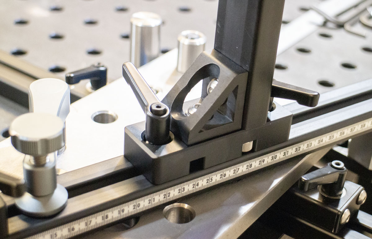
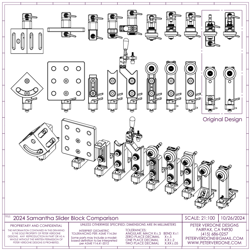
At first, I was looking at a full monolithic approach to the slide. Geometrically, a single part can more easily control several variables at once. This works against the concept of reconfigurability though. Over time, I came up with something that should prove much better. A breadboard face. The system is still very extendable but the single piece slider and bracket ensure that the 2.000″x0.625″ pinout and 0.321 slot are centered to the rail and aligned with vertical. This is similar to other parts on the fixture as well as the 2023 PVD Wheel Tool. Keeping the sliding base and vertical mount as one piece reduces stack up and fit issues negated.
The sliding bracket is optimized for using BuildPro T51003, 3-hole Channel Block, 6.3 x 1.6 x 0.625. That gives me an inexpensive ($16.50 ea.) and precise way of using more 16mm steel plate to the design. It also adds to the ecosystem compatibility that I’ve been developing. Steel Legos are good.
Much more massive! Much more precise.
As many options, on hand or imagined, were modeled to ensure that these new parts would add significant value to the fixture. Additional BuildPro components, like the T51009 and T50121, and straight edges can be placed on the slide. 8020 1575 profile extrusion can still be used if need be, with three 0.625″ bored holes in place, aided by the 0.321″ slot (hidden from view here) that can hold a Delrin key also fit into the profile. Even more custom fixturing is easy to add with a solid and precise footing, like the seat tube support.
The sliding block was made as solid and massive as possible given the hardware clearances and interface required. These are really stout components. It’s a lot of aluminum and steel sitting on the rail. I want stability, rigidity, and the maximum material on hand for odd modifications.
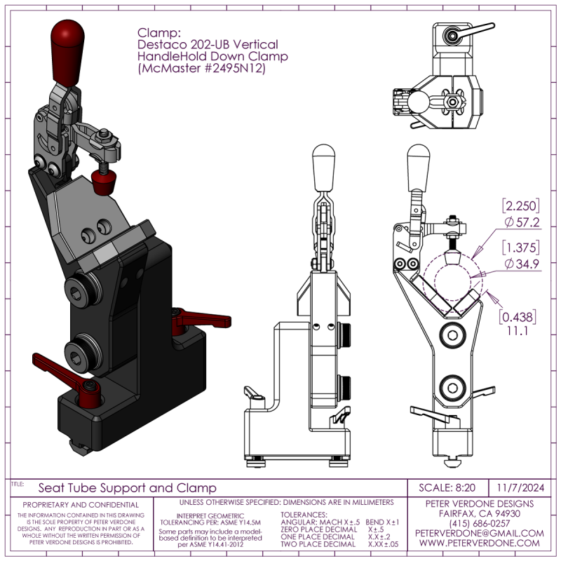
The seat tube vee block support got redesigned with a more formidable vee block element. This was a hassle to machine at precision on the manual mill but it got done well enough to use. This provided a prototype that was the basis for a final and more well thought out version that is currently being cut at another machine shop. It’s going to be a marvelous upgrade.
The clamp is a Destaco 202-UB vertical clamp for rail mount (McMaster 2495N12, $20.59). This is a lower profile and more elegant mount than you typically see for a clamp of this type. It isn’t seen in the photos as it’s currently on order and should be complete in a few days.
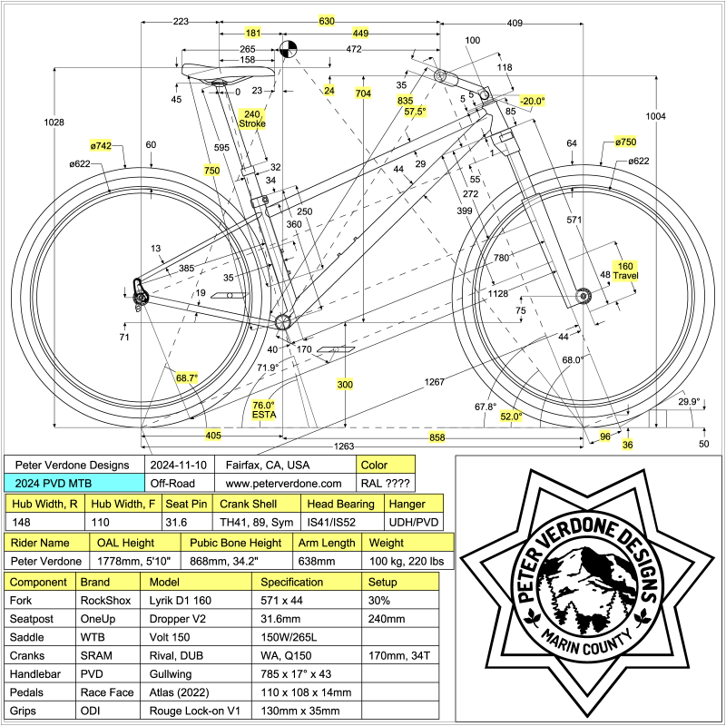
The fixture is shown set up for the next frame that I’ll be building. An updated 160mm hardtail mountain bike. The calculator sheet for the fixture setup is below. These are early numbers but pretty close. It will be exciting if I can squeeze the 68 degree head tube angle into the frame and still have it present well.
Notice that the calculator now uses horizontal front and rear center. This is big. Previously, I used direct front and rear centers as driving parameters for defining the bike and calculating fixture setup. I had been on the fence for a few years but had not made the change. I finally have. I’m now glad that I finally did.
Now when I change the crank shell height, the weight distribution remains. That isn’t the case with direct centers. My center of gravity moves up or down in the bike but the wheels remain where they are. I can still adjust the measures for the centers to tune the stability of the bike as it relates to the COG but that is deliberate rather than accidental.

