I got caught up in a machine of my own making. A machine built to catch me exactly as it did. This is my Accountability Mechanism. It swallowed me whole, right after my previous post on handlebars.
I thought that I had completed the work required on the handlebar component of the new bike project before making the last video, but I was wrong. I produced a calculator and designed a tool. Great. The issue was that I hadn’t dug in and updated the handlebar models that I’m using. Sure, the bars looked (and are) correct, but the architecture in the modeling software was several years old.
I re-watched the video from the previous post and saw only negligence.
That hurt. I want to show good work. I want to display my best, not my ‘getting by’. Since showing up well is part of my accountability mechanism, I took another week to dig into my models and make them right. Go deeper to do better. In a past era, this would be called fucking MAGIC….or even possession. Dark arts make people do hard things.
The primary fix was to finish construction a master part file that would be used by all of the associated parts in the handlebar sub-assemblies. This means that one file contains all of the equations, construction geometry and certain surfaces. I’ve done this for my frame model over the past few years but hadn’t gotten around to doing it for the handlebars.
I have worked with SolidWorks (and AutoCAD before that) for over 25 years. I’ve tried just about every strategy for working with complex assembly geometries, in bicycles and skateboard trucks as well as with my work in a university physics department. Most strategies will have both advantages and shortcomings. Some are generally better than others. Sketch-based masters may work fine for simple parts or as a rapid shortcut when beginning a project but tend to fail miserably when configurations change significantly or when assemblies are complex. Sketches are also two dimensional rather than three. ‘In context’ references made in assemblies can work but only on simple designs without sub-assemblies of sub-assemblies or large configuration differences. Those associations will only function one level down at best.
Why a master part?
A master part is a part like any other. It can contain equations, geometries, surfaces, bodies, materials, sketches, etc. These should be as detailed as possible for most parts in the assembly universe. There can be as many configurations as you please.
If I recall correctly, it was Ronen Sarig that suggested I try a master part for my designs. Ronen has worked for quite a few serious tech companies in the Bay Area as an electrical and mechanical engineer so I take his opinion seriously. This time, he was right. I tend to work alone and don’t get to benefit from large teams of experts around me.
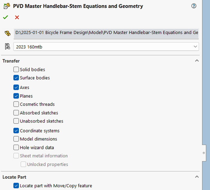
In this screenshot, the master part is being inserted into the slave part. Notice that we can select what information imports into the file. I don’t use sketches so I don’t bring them in. Every now and then I’ll use solids and surfaces, but here only surfaces. I always bring in planes, axes, and coordinate systems. In different configurations of the slave part, different configurations of the master part can be used.
What is glaring is that equation values are missing from the transfer selection. That would be an amazing thing to be able to pass to other files but has missed the developers for some reason. Fix that!!
What we see in the feature tree after the part is inserted is below. Because I’m old (ugh) I refer to the coordinate systems as UCS (User Coordinate System). That’s leftover from the last century when we used AutoCAD for mechanical design. Just a relic in my closet. There are nine of them in the handlebar system…so far.
Any change made to this master part will immediately propagate to ALL parts that are using it, eliminating update failures seen using ‘in-context’ associations. In the complex assemblies that I produce, this is critical. I may have 30 parts that use a particular parameter, each with maybe 30 features. If I change that parameter in 29 parts, but forget to update one, I could have a catastrophic (read expensive and time consuming) result. Using a master part helps ensure that that mistake isn’t made. Change propagation is ensured!
Since there are construction geometries in the master part, I can also define coordinate systems for easy placement within slave parts so that sensible part origins are used. Nothing says “amateur architecture” more than a part with a nonsense origin. When using the master part within assemblies, mating parts can be done simply by connecting coordinate systems to origins. This keeps mate count down, adding to dependability. I’ve gotten to the point where I mate the master to the assembly origin sensibly then everything else is mated to the construction geometry or coordinate systems in the master part. It just works.
Interestingly, more than one ‘master’ part can be inserted into a part with as many bodies contained as you care to have. It’s a strange thought. Sometimes, I insert bodies of parts that I’m ‘tracing’ only to delete them when I’m done. This keeps me from having to have more than one file open at a time.
Anyone that has worked with equations in SolidWorks knows how slow the computer system becomes when updating or making any change to a part that is built using them. I may have two to three hundred equations and associations in a big model. The system crawls to a halt when one feature is changed, even in the smallest way. If I contain all of that processing and solving in a master part, it is done outside of the part, conserving the computer’s resources. It is a lighter way of working on a part that would otherwise need equations and assemblies open to function. When I realized this, I committed entirely to this method.
The Handlebar master part has 65 equations so far. The frame master part has just 226. This sounds like a lot but they have accumulated over the last decade, slowly growing in count as my designs have focused on far more granular geometries. This gives a single repository for parameters and calculations are turned into valuable dimensions that can extend to any part.
Entering equations in SolidWorks is a nonsensical pain in the ass. It’s easier to use a text editor to work with large formula. I like to store most math in spreadsheets and bridge to SW with text editors. Be careful, though. I made a post in 2022 about the very different logic that SolidWorks uses than common (VBA) spreadsheet programs.
Certain complex surfaces, that many parts depend on, like tapered head tubes or steerer binders are stored in position in the master part. Those are used for a surface cut on top tubes, down tubes, and handlebar struts. Here a strut is cut with a surface from the master part that is aligned in a complex way, separate from what the obvious origin of the part is.
One issue that I have with this method is that axes don’t translate from the master part to the slave part. I have to use planes to define axes in the slave part. I suspect that it has something to do with directions of the axes as produced by the normal of the planes that create it. I’d like to know if someone can tell me the answer.
However, In some testing after producing the video and most of this post, I’ve tried to just use the geometry of the master directly in the features of the parts. This seemed to be problematic earlier on as deleting the master part from the part will destroy the features built with them. This is something that should be fixed in SolidWorks but hasn’t been. Still, once it occurred to me that I could port multiple master parts into the part and perform a surgical handoff, I got more comfortable with the concept. Then, you re-assign features to the new master and then delete the old master. This requires some focus and time but master parts shouldn’t be getting swapped out too often. I’m going to implement this to more of my parts in the next few months to clean them up and make them more efficient.
I need to look into whether a table-driven master part can work well. Generally, table-driven parts work so slowly and are so cumbersome they are not worth using. If I’m working with only the master part that way it could prove valuable but that would depend on system performance. I wish that SolidWorks would make it quicker and easier to use spreadsheet-based equations, most importantly so that I don’t have to open SolidWorks to revise an entire assembly of parts.
Below is a screenshot of some of the handier construction geometries, from the master part file.
Here are all of the construction geometries from the master part. It’s a lot and this is only shown for this post. I would never need this mess on my screen.
This may seem trivial. Who cares about all of this? Speaking from experience, more folks should. I’m able to produce precise fits for unitized handlebars and associated tooling because of these methods. Building the designs for these becomes far easier. Other options are either impossible or so tenuous that they can’t become commonplace or industrialized. On a single part level, geometries that would be time consuming and painful are quickly available.
Now we can take a look at the new tooling as it went into use this week.
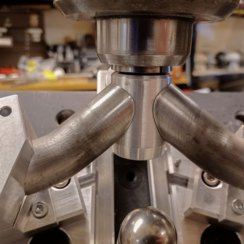
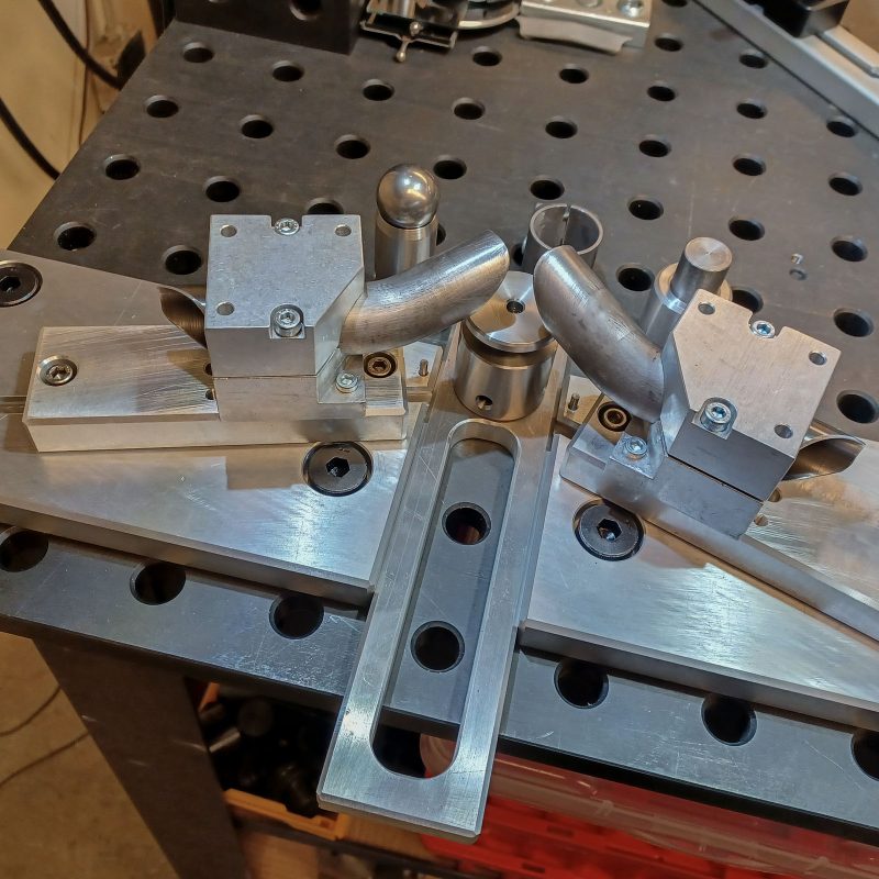
Photos of cutting parts using the new tooling and welding setup for the handlebars should help folks see why all of this is different:
I use a 1.125″ dummy cutter to check the balance of the cut while still set up in the mill. After the cut, I clean and debur the struts and replace them in position. It also helps move the struts closer to the axis for a tighter fit than the hole saw produces. This cut came out great with the struts looking exactly as they should.
This cool custom jack I made rests under the struts ensuring that they meet the binder just right. This is crucial in making these types of handlebars as any deviation here will be stared at throughout the ride.
The plates transfer to the welding table and are ready for the steerer lug fixture to be set up for welding. Setup on the table works exactly like on the mill. Legos.
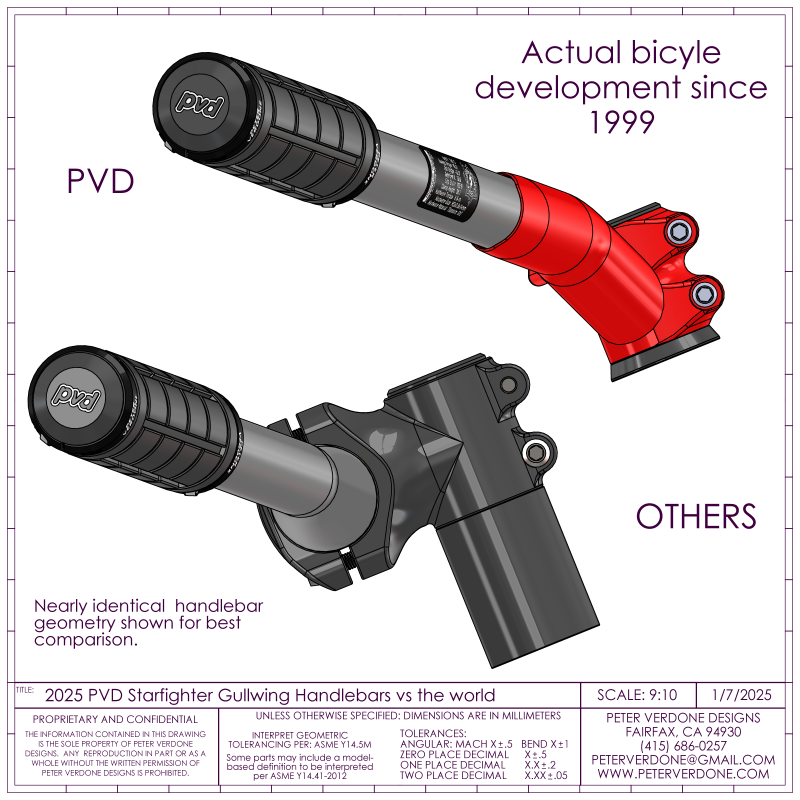
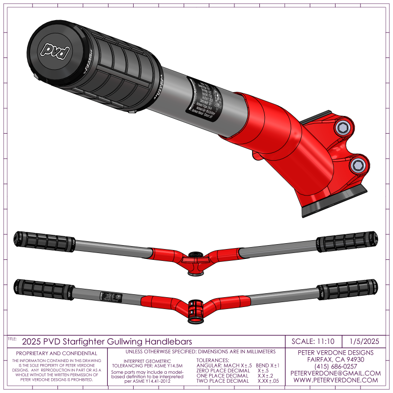
When you have a really good design system in place, prints like below are quick and easy to produce. We get real value from this as we can understand deeply what we are doing and how to contextualize it.


