Damping:
(Ohlins)Before going any further with the topic of damping, a very useful graphical explanation should be understood. Essentially this is how modern motorcycle cartridge fork and rear shock damping works. This image was scanned from the SAE Shock Absorber Handbook (p.244). The horizontal scale (Q) denotes velocity, while the vertical scale (P) denotes damping force. Note that damping force NEVER decreases as velocity increases.
Oil flow is used to create damping. This flow is created by the damping rod displacing fluid in one part of the shock and moving it to another part of the shock. The damper rod area multiplied by the total travel available is the total volume of fluid that will ever be displaced.
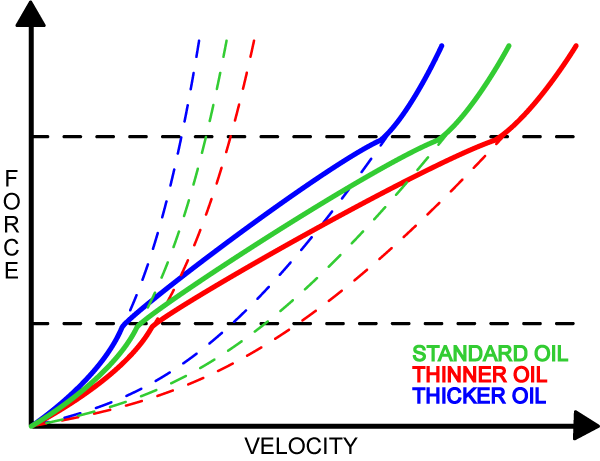
A traditional damper rod type fork would just follow Curve A, or the damping force created by oil passing through a simple slow speed orifice. Curve B, while similar in shape to Curve A, represent the damping curve created by the combination of the simple slow speed orifice and the high speed valve orifices (sans shims). With the introduction of shims over the high speed valve, the true damping is represented by the curve in BOLD. Initially, the damping follows Curve A until enough force is created to start bending the shims open. The shape of the shim stack controls initiation and the shape of the curve through the Transition Region. Once enough force has been generated to bend the shims fully open, the damping curve then follows Curve B.
Lower viscosity oils increase the proportion and higher viscosity oils decrease the proportion of the velocity scale (Q). In other words, oil viscosity effects every part of the damping curve. Oil is very, very, very important.

All of this explains why it is so important for the performance rider or racer to have a cartridge fork and a quality rear shock. With these components, each individual part of these curves can be controlled and tuned.
Also, Honda HMAS valves (and Ohlins, I believe) are designed so that the actual damping curve indeed joins up with Curve B during actual use, while many aftermarket "high flow" valves never escape the Transition Region.
This mathematics site and here gives a very mathematical explanation of what damping is from a mathmatics point of view.
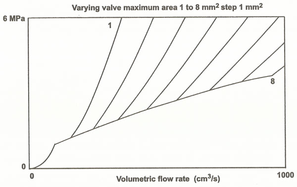
Tuning the damping. Illustrations taken from p. 284-6 of SAE Shock Absorber Manual.
* Effect of adjusting the slow speed orfice or needle
* Effect of changing the main shims of the stack
* Effect of changing the shim stack configuration
* Effect of combined bleed and valve orfice size.

This site has not been
updated since Fall 2006.
Since then, all new projects
have been place on my wiki
site.
If you like what you see on
this site, Make sure to go
to the wiki for even better
projects.